We found that the hull had been cut into at some point to replace the lower part of the saildrive by lowering it through the hull, and that cutout had not been properly repaired. The leak was water getting through the poor repair job. The cutout would have been necessary to lower the saildrive because it would not have fit down through the opening in the hull as constructed by Tartan. BTW, the proper way to replace the saildrive is to bring it up through the hull into the interior of the boat...no cutout required as it would fit to bring it up through the hull opening.
The first clue to the hidden problem appeared once the saildrive was removed. That disclosed a poorly done application of fiberglass. The photos below show some of this.
Cleaning off the fiberglass patch, it was apparent that it was done with polyester resin...bad choice for an epoxy hull as polyester will not bond to epoxy. Also, some of the resin had not fully hardened. As the patch was removed, it became apparent that the cutout resulted in opening up a passage for water from the water side of the saildrive into the hull interior. This had been patched very poorly and eventually the cause of the leak.
 |
| After removing some of the patch, the hole near the center of this photo showed up...the likely path of the water leaking into the bilge. |
 |
| These two pieces had been cut off and then put back in place. They came loose as the fiberglass was removed. |
 |
| This photo shows how the pieces cut away covered the circular part of the saildrive where it mounted to the upper gear box. |
 |
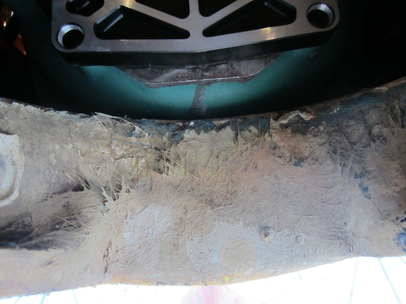
| The saw marks for the cutout and the openings into the hull are apparent in this photo taken after the fiberglass patch was removed. |
Once the patch work was cleaned of the epoxy hull, work could begin on repairing it properly.
 |
| First step was to glass the opening. |
Tartan sent us a template that they use for cutting the hole, but the template did not fit into the circular saildrive mount space. They must have changed the design a bit since hull #2. Paul and Ken took some measurements on the saildrive and mount to determine the hole location and drilled some pilot holes based on their findings before cutting the actual hole.
 |
| Here is the new hole as seen from the outside (compare to photo above) |
 |
| and from the inside. |
 |
| Saildrive with fresh coat of paint ready for install. |
The saildrive installation went well. The tricky part was getting the spline to line up with where it went into the back of the engine. This involved leveraging the engine up and sliding it back to the spline and then turning the engine crank using the fan belt until the spline was able enter into the back of the engine. Paul was on the lever, Ken on the engine and I had the easy job of checking the alignment.
 |
| The hole size and location was perfect with about a half inch of clearance front and back. |